ARM7 processors are high end micro controllers used in mobile phones. They are very powerful (60Mhz clock speed, single word RISC instructions). See http://en.wikipedia.org/wiki/ARM_architecture
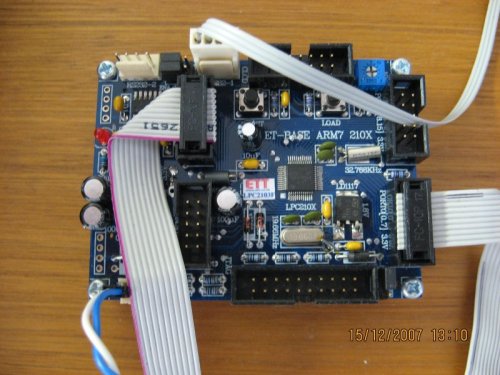
I wrote this program due to the lack of example source code for the LPC21XX ARM7 processor. I pissed around for 3 weeks with the ET-BASE ARM7 210X documentation (getting bum steered at times), until I was able to create this application that works with a GCC based tool chain.
This program blinks two LED's. One LED is blinked by a foreground process, and the other by an interrupt service routine (ISR). The foreground program toggles port P0.0 at a given rate determined by delay loop. This part of the program is your traditional blinky LED program. The background (timer0) is implemented to output a pulse train as per the blink_sequence variable (in main.c). The blink sequence is: short blink, medium blink, long blink... wait
Timer0 is configured as "external output match" mode. The timer0 counter, counts up to a given number. When it is reached, it resets the counter and interrupts. The timer0 ISR then toggles the match pin state (P0.5). However, the micro will do this change on the next interrupt. This mechanism provides a gitch free pulse train with no transistion latancy caused by instructions.